
Overview
What You Will Learn
- Introduction of ST microcontrollers and ARM structure
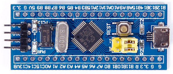
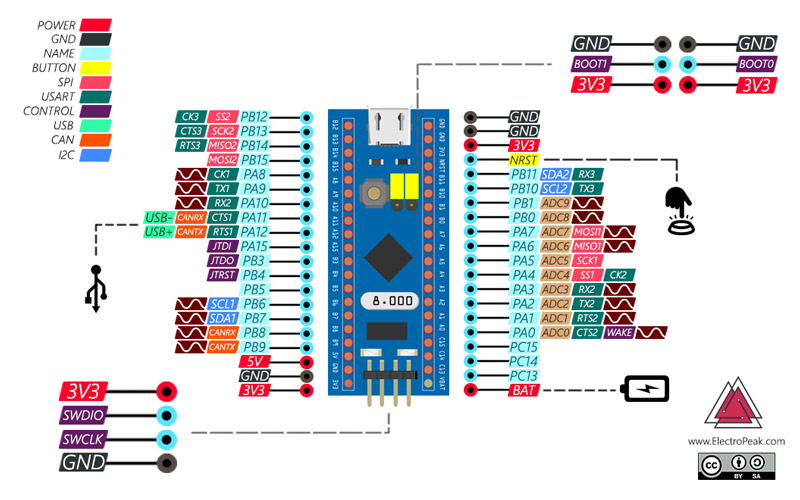
- Introduction of STM32F103C8T6 board
- The required software to work with STM32 microcontrollers
- How to program STM32F103C8T6 board
- Make a blinker using STM32F103C8T6
Introduction to ARM and STM Microcontrollers
| Code | Core | Max Freq(MHz) | Max Flash(KB) | Max SRAM(KB) | Target |
|---|---|---|---|---|---|
| L0 | CortexM0+ | 32 | 192 | 20 | Ultra Low Power |
| F0 | CortexM0 | 48 | 256 | 32 | Mainstream |
| F3 | CortexM4 | 72 | 512 | 80 | Mainstream |
| L1 | CortexM3 | 32 | 512 | 80 | Ultra Low Power |
| F1 | CortexM3 | 72 | 1024 | 96 | Mainstream |
| F2 | CortexM3 | 120 | 1024 | 128 | High Performance |
| L4 | CortexM4 | 80 | 1024 | 320 | Ultra Low Power |
| F7 | CortexM7 | 216 | 2048 | 512 | High Performance |
| H7 | CortexM7 | 400 | 2048 | 1048 | High Performance |
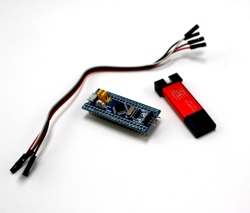
Required Materials
Hardware Components
Software Apps
STM32F103C8T6 Features STM32F103C8T6 is a good choice to start working with STM microcontrollers due to its low price and availability. The general specifications of this microcontroller are as follows:
- 32bits CortexM3
- microcontroller
- 64 KB flash memory
- 20 KB SRAM memory
- The maximum
- processing speed of 72 MHz
- 37 GPIO pins
- 12 PWM channels
- Having 10 12–bits ADC channels
- Supporting 2 units of
- I2C, 2 units of SPI and 3 units of UART
- Having 3 16–bits timer
- Supporting CAN 2.0 protocol
This microcontroller is available in modular and ready-to-use form
Getting Started with STM32F103C8T6

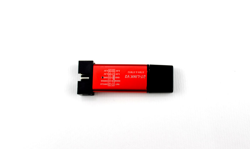
Programming STM Microcontrollers Using ST-Link
In this method, the ST–Link V2.0 tool for STM microcontrollers is used. Before programming, you need to download and install the drivers required by ST-Link from here.
Programming STM Microcontrollers Using USB to TTL Module
Note
Note
Make a Blinker using STM32F103C8T6
In this project, we use the LED on the board, this LED is connected to the PC13 pin.
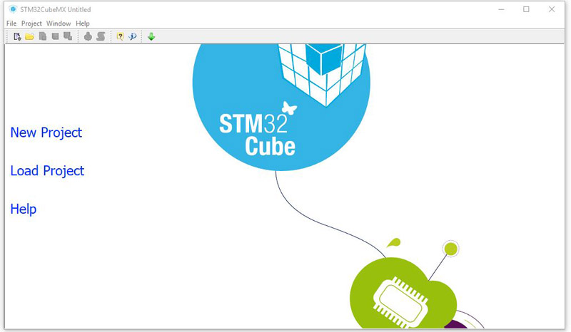
Now follow the steps below in STM32 CubeMX:
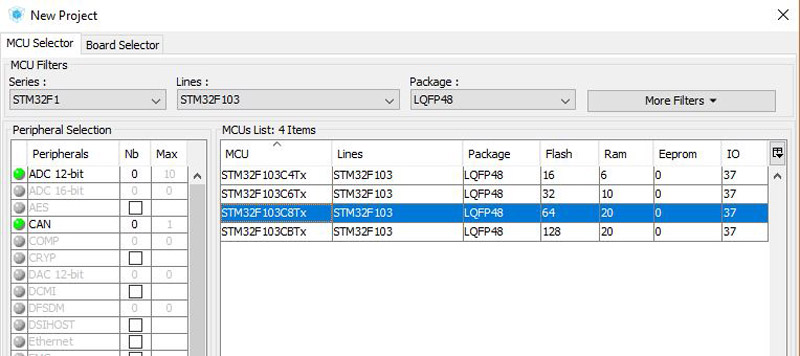
First Step. Selecting the Microcontroller:
After starting a new project, the list of microcontrollers will appear. Find STM32F103C8T6 and select it

Third Step. Clock Configurations
Fourth Step. Seeing the Result
Select the Open project option and your project will open in Keil.
Now you are ready to start programming.
Code
Note
/**
  ******************************************************************************
  * LED Test
  * Description        : Saeed Hosseini @ Electropeak
Home
  ******************************************************************************
  *
  * COPYRIGHT(c) 2019 STMicroelectronics
  *
  * Redistribution and use in source and binary forms, with or without modification,
  * are permitted provided that the following conditions are met:
  *   1. Redistributions of source code must retain the above copyright notice,
  *      this list of conditions and the following disclaimer.
  *   2. Redistributions in binary form must reproduce the above copyright notice,
  *      this list of conditions and the following disclaimer in the documentation
  *      and/or other materials provided with the distribution.
  *   3. Neither the name of STMicroelectronics nor the names of its contributors
  *      may be used to endorse or promote products derived from this software
  *      without specific prior written permission.
  *
  * THIS SOFTWARE IS PROVIDED BY THE COPYRIGHT HOLDERS AND CONTRIBUTORS "AS IS"
  * AND ANY EXPRESS OR IMPLIED WARRANTIES, INCLUDING, BUT NOT LIMITED TO, THE
  * IMPLIED WARRANTIES OF MERCHANTABILITY AND FITNESS FOR A PARTICULAR PURPOSE ARE
  * DISCLAIMED. IN NO EVENT SHALL THE COPYRIGHT HOLDER OR CONTRIBUTORS BE LIABLE
  * FOR ANY DIRECT, INDIRECT, INCIDENTAL, SPECIAL, EXEMPLARY, OR CONSEQUENTIAL
  * DAMAGES (INCLUDING, BUT NOT LIMITED TO, PROCUREMENT OF SUBSTITUTE GOODS OR
  * SERVICES; LOSS OF USE, DATA, OR PROFITS; OR BUSINESS INTERRUPTION) HOWEVER
  * CAUSED AND ON ANY THEORY OF LIABILITY, WHETHER IN CONTRACT, STRICT LIABILITY,
  * OR TORT (INCLUDING NEGLIGENCE OR OTHERWISE) ARISING IN ANY WAY OUT OF THE USE
  * OF THIS SOFTWARE, EVEN IF ADVISED OF THE POSSIBILITY OF SUCH DAMAGE.
  *
  ******************************************************************************
  */
/* Includes ------------------------------------------------------------------*/
#include "main.h"
#include "stm32f1xx_hal.h"

/* USER CODE BEGIN Includes */

/* USER CODE END Includes */

/* Private variables ---------------------------------------------------------*/

/* USER CODE BEGIN PV */
/* Private variables ---------------------------------------------------------*/

/* USER CODE END PV */

/* Private function prototypes -----------------------------------------------*/
void SystemClock_Config(void);
void Error_Handler(void);
static void MX_GPIO_Init(void);

/* USER CODE BEGIN PFP */
/* Private function prototypes -----------------------------------------------*/

/* USER CODE END PFP */

/* USER CODE BEGIN 0 */

/* USER CODE END 0 */

int main(void)
{

  /* USER CODE BEGIN 1 */

  /* USER CODE END 1 */

  /* MCU Configuration----------------------------------------------------------*/

  /* Reset of all peripherals, Initializes the Flash interface and the Systick. */
  HAL_Init();

  /* Configure the system clock */
  SystemClock_Config();

  /* Initialize all configured peripherals */
  MX_GPIO_Init();

  /* USER CODE BEGIN 2 */

  /* USER CODE END 2 */

  /* Infinite loop */
  /* USER CODE BEGIN WHILE */
  while (1)
  {
  /* USER CODE END WHILE */
		HAL_GPIO_TogglePin(LED_GPIO_Port,LED_Pin);
		HAL_Delay(50);
  /* USER CODE BEGIN 3 */

  }
  /* USER CODE END 3 */

}

/** System Clock Configuration
*/
void SystemClock_Config(void)
{

  RCC_OscInitTypeDef RCC_OscInitStruct;
  RCC_ClkInitTypeDef RCC_ClkInitStruct;

    /**Initializes the CPU, AHB and APB busses clocks
    */
  RCC_OscInitStruct.OscillatorType = RCC_OSCILLATORTYPE_HSI;
  RCC_OscInitStruct.HSIState = RCC_HSI_ON;
  RCC_OscInitStruct.HSICalibrationValue = 16;
  RCC_OscInitStruct.PLL.PLLState = RCC_PLL_NONE;
  if (HAL_RCC_OscConfig(&RCC_OscInitStruct) != HAL_OK)
  {
    Error_Handler();
  }

    /**Initializes the CPU, AHB and APB busses clocks
    */
  RCC_ClkInitStruct.ClockType = RCC_CLOCKTYPE_HCLK|RCC_CLOCKTYPE_SYSCLK
                              |RCC_CLOCKTYPE_PCLK1|RCC_CLOCKTYPE_PCLK2;
  RCC_ClkInitStruct.SYSCLKSource = RCC_SYSCLKSOURCE_HSI;
  RCC_ClkInitStruct.AHBCLKDivider = RCC_SYSCLK_DIV1;
  RCC_ClkInitStruct.APB1CLKDivider = RCC_HCLK_DIV1;
  RCC_ClkInitStruct.APB2CLKDivider = RCC_HCLK_DIV1;

  if (HAL_RCC_ClockConfig(&RCC_ClkInitStruct, FLASH_LATENCY_0) != HAL_OK)
  {
    Error_Handler();
  }

    /**Configure the Systick interrupt time
    */
  HAL_SYSTICK_Config(HAL_RCC_GetHCLKFreq()/1000);

    /**Configure the Systick
    */
  HAL_SYSTICK_CLKSourceConfig(SYSTICK_CLKSOURCE_HCLK);

  /* SysTick_IRQn interrupt configuration */
  HAL_NVIC_SetPriority(SysTick_IRQn, 0, 0);
}

/** Configure pins as
        * Analog
        * Input
        * Output
        * EVENT_OUT
        * EXTI
*/
static void MX_GPIO_Init(void)
{

  GPIO_InitTypeDef GPIO_InitStruct;

  /* GPIO Ports Clock Enable */
  __HAL_RCC_GPIOC_CLK_ENABLE();
  __HAL_RCC_GPIOA_CLK_ENABLE();

  /*Configure GPIO pin Output Level */
  HAL_GPIO_WritePin(LED_GPIO_Port, LED_Pin, GPIO_PIN_RESET);

  /*Configure GPIO pin : LED_Pin */
  GPIO_InitStruct.Pin = LED_Pin;
  GPIO_InitStruct.Mode = GPIO_MODE_OUTPUT_PP;
  GPIO_InitStruct.Speed = GPIO_SPEED_FREQ_LOW;
  HAL_GPIO_Init(LED_GPIO_Port, &GPIO_InitStruct);

}

/* USER CODE BEGIN 4 */

/* USER CODE END 4 */

/**
  * @brief  This function is executed in case of error occurrence.
  * @param  None
  * @retval None
  */
void Error_Handler(void)
{
  /* USER CODE BEGIN Error_Handler */
  /* User can add his own implementation to report the HAL error return state */
  while(1)
  {
  }
  /* USER CODE END Error_Handler */
}

#ifdef USE_FULL_ASSERT

/**
   * @brief Reports the name of the source file and the source line number
   * where the assert_param error has occurred.
   * @param file: pointer to the source file name
   * @param line: assert_param error line source number
   * @retval None
   */
void assert_failed(uint8_t* file, uint32_t line)
{
  /* USER CODE BEGIN 6 */
  /* User can add his own implementation to report the file name and line number,
    ex: printf("Wrong parameters value: file %s on line %d\r\n", file, line) */
  /* USER CODE END 6 */

}

#endif

/**
  * @}
  */

/**
  * @}
*/

/************************ (C) COPYRIGHT STMicroelectronics *****END OF FILE****/HAL_Delay function (50); function causes a delay of 50 ms.
To learn more about the full functions available in the HAL library, you can read here. What’s Next?
- Try turning the LED on and off using a key by inserting another GPIO pin as input and connecting a key.
