

Overview
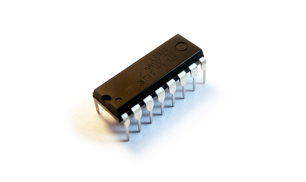
In this article, we want to take a deeper look at L293D. L293D is the most widely used IC to drive motors and it is necessary to know it’s theory, diagram, simulation, and pinout. Here we will discuss all these subjects.
L293D & Motors; What's the story?
L293D Features and Specifications
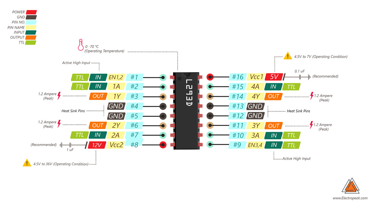
The L293 and L293D devices are quadruple high current half-H drivers. The L293 is designed to provide bidirectional drive currents of up to 1 A at voltages from 4.5 V to 36 V. The L293D is designed to provide bidirectional drive currents of up to 600-mA at voltages from 4.5 V to 36 V. Both devices are designed to drive inductive loads such as relays, solenoids, DC and bipolar stepping motors, as well as other high current / high voltage loads in positive supply applications.
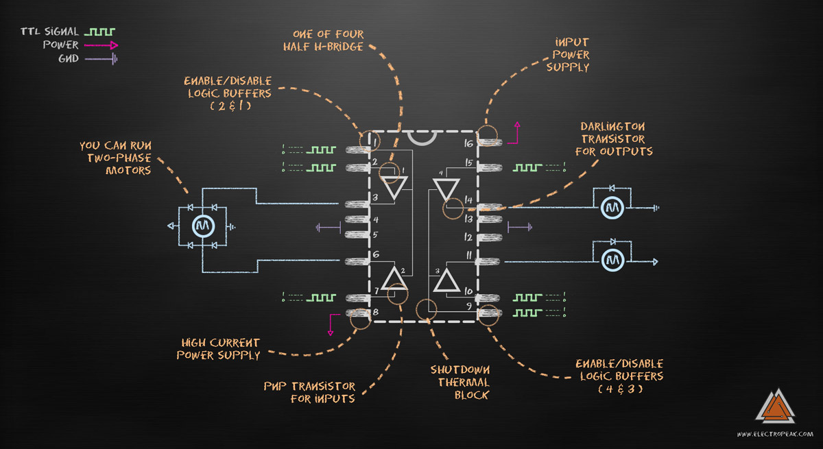
Each output is a complete totem-pole drive circuit, with a Darlington transistor sink and a pseudo- Darlington source. Drivers are enabled in pairs, with drivers 1 and 2 enabled by 1,2EN and drivers 3 and 4 enabled by 3,4EN. L293 and L293D are characterized for operation from 0°C to 70°C.
Other important L293D features are:
- Wide Supply-Voltage Range: 4.5 V to 36 V
- Separate Input-Logic Supply
- Internal ESD Protection
- High-Noise-Immunity Inputs
- Output Current 1 A Per Channel (600 mA for L293D)
- Peak Output Current 2 A Per Channel (1.2 A for L293D)
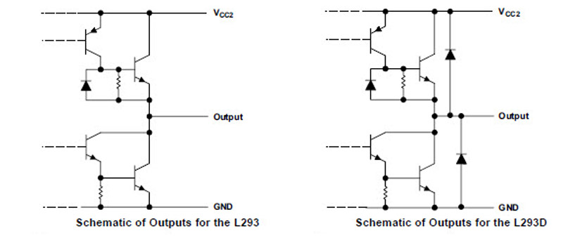
- Output Clamp Diodes for Inductive Transient Suppression (L293D)
Overall L293D Diagram
Simulation - L293
H-bridge & Half-H
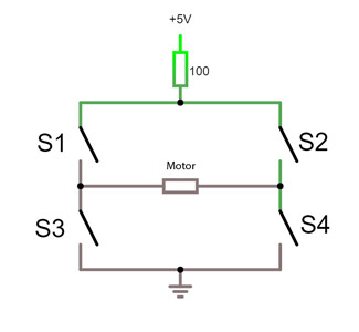
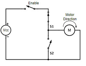
An H bridge is an electronic circuit that enables a voltage to be applied across a load in opposite direction. These circuits are often used in robotics and other applications to allow DC motors to run forwards or backward.
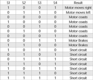
The term H bridge is derived from the typical graphical representation of such a circuit. An H bridge is built with four switches (solid-state or mechanical). When the switches S1 and S4 (according to the first figure) are closed (and S2 and S3 are open) a positive voltage will be applied across the motor. By opening S1 and S4 switches and closing S2 and S3 switches, this voltage is reversed, allowing reverse operation of the motor.
Using the nomenclature above, the switches S1 and S2 should never be closed at the same time, as this would cause a short circuit on the input voltage source. The same applies to the switches S3 and S4. This condition is known as shoot-through.
Simulation – H-Bridge- Guide
Simulation – Half-H
Darlington Transistor
In electronics, the Darlington transistor (commonly called a Darlington pair) is a compound structure of a particular design made by two bipolar transistors connected in such a way that the current amplified by the first transistor is amplified further by the second one. This configuration gives a much higher current gain than each transistor taken separately.
Invented in 1953 by Sidney Darlington
If we see the Darlington Transistor’s symbol we can clearly see how two transistors are connected. In the below images, two type of Darlington transistor is shown. On the left side it is NPN Darlington and on the other side, it is PNP Darlington. We can see NPN Darlington consist of two NPN transistors, and PNP Darlington consists of two PNP transistors. The first transistor’s emitter is directly connected across the base of another transistor, also the collector of the two transistors are connected together. This configuration is used for both NPN and PNP Darlington transistors. In this configuration, the pair or the Darlington transistor produces much higher gain and large amplification capabilities.
Simulation – Darlington Transistor
L293D Pinout
L293 & L293D; What's the difference?
What is the difference between L293 and L293D? letter D in the name indicates an internally fitted diode and it means that we don’t need to add any external components. This is the main difference. If you look at the data sheet, you could see some other difference like Outputs current. Also, The Continuous current in L293 Outputs is 1A and in L293D Outputs is 600 mA. The Peak current in L293 Outputs is 2ampere and in L293D Outputs is 1.2 A

Comments (5)
Excelent information!
So glad you enjoyed it!
The comment in the paragraph “Using the nomenclature above, the switches S1 and S2 should never be closed at the same time, as this would cause a short circuit…” is wrong. It doesn’t agree with the diagram or the table. The two pairs of switches that should never be closed at the same time are S1/S3 and S2/S4.
Closing S1/S2 or S3/S4 will brake the motor because it shorts the motor terminals.
Hi,
It seems you’re right! Thanks for your attention.
Quite entertaining god work